
Dobson Troubleshooting Guide
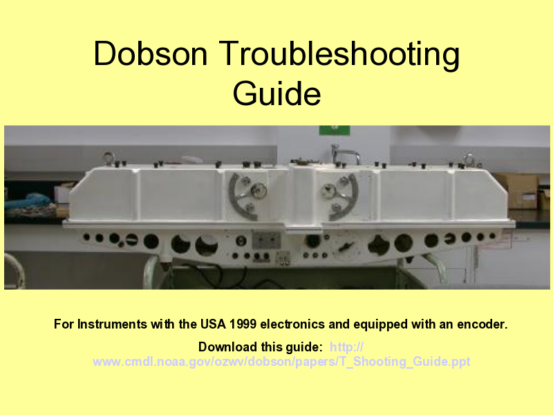
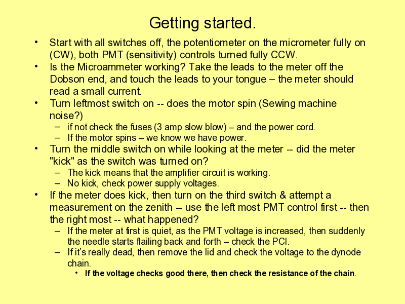
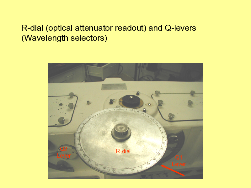
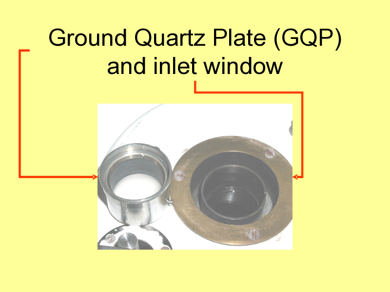
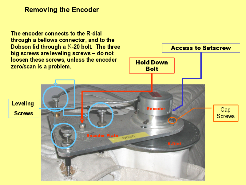
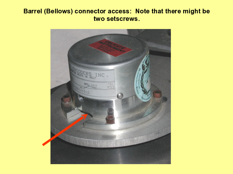
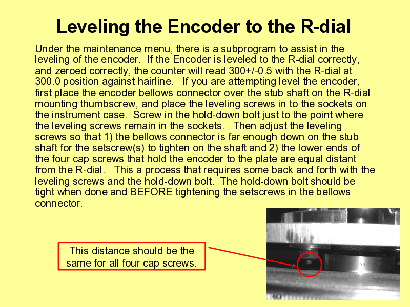
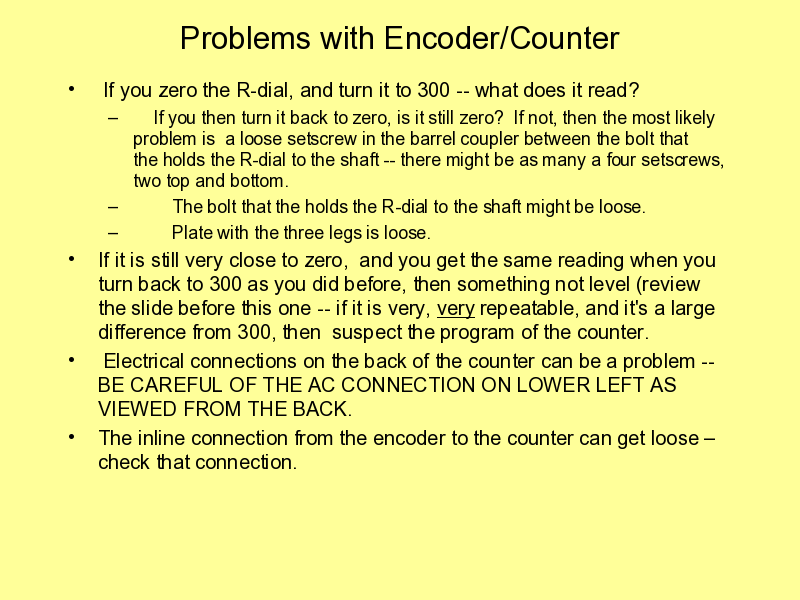
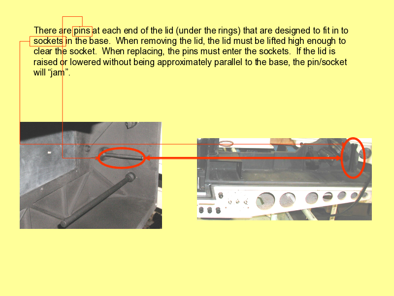
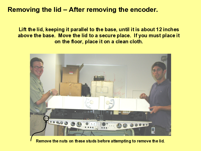
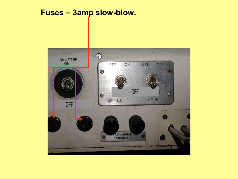
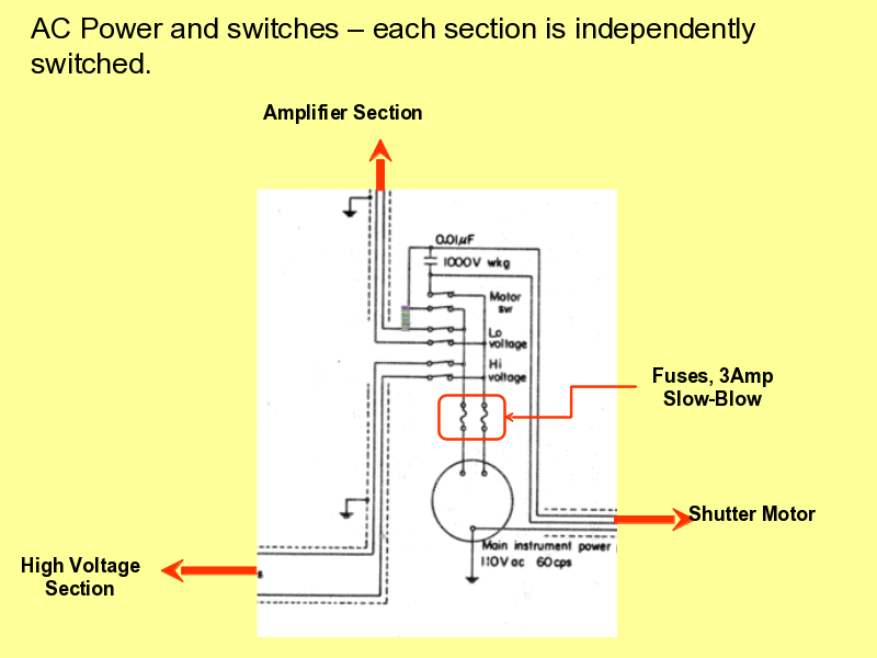
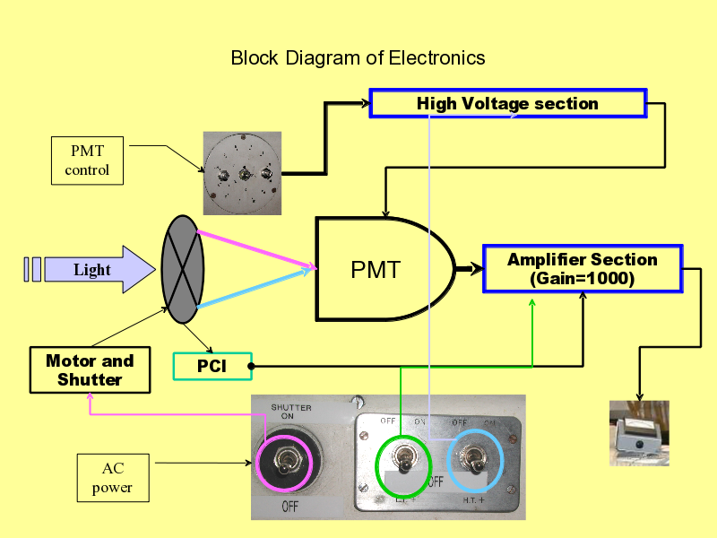
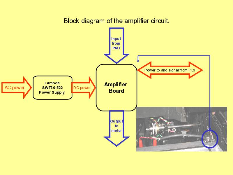
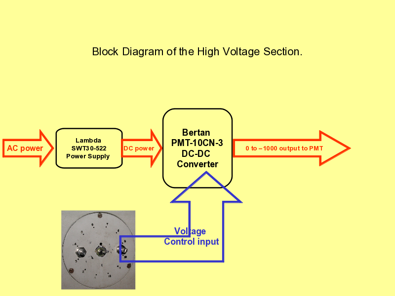
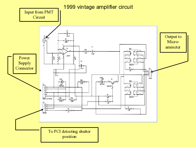
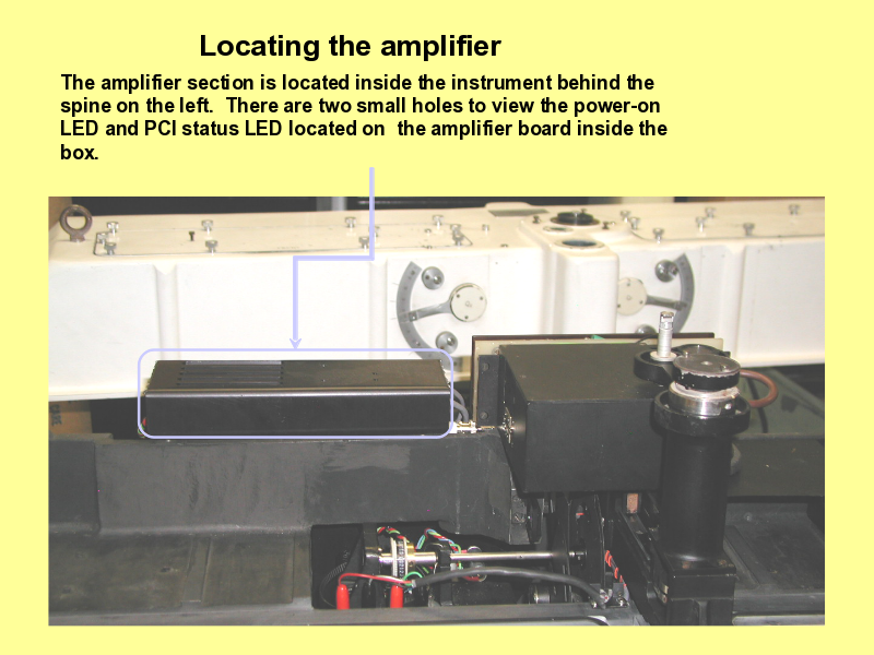
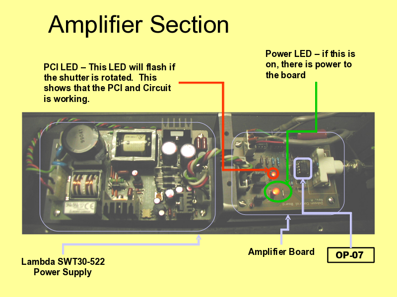
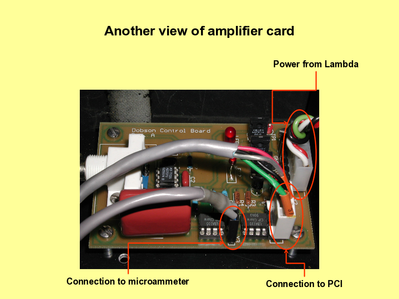
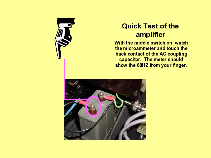
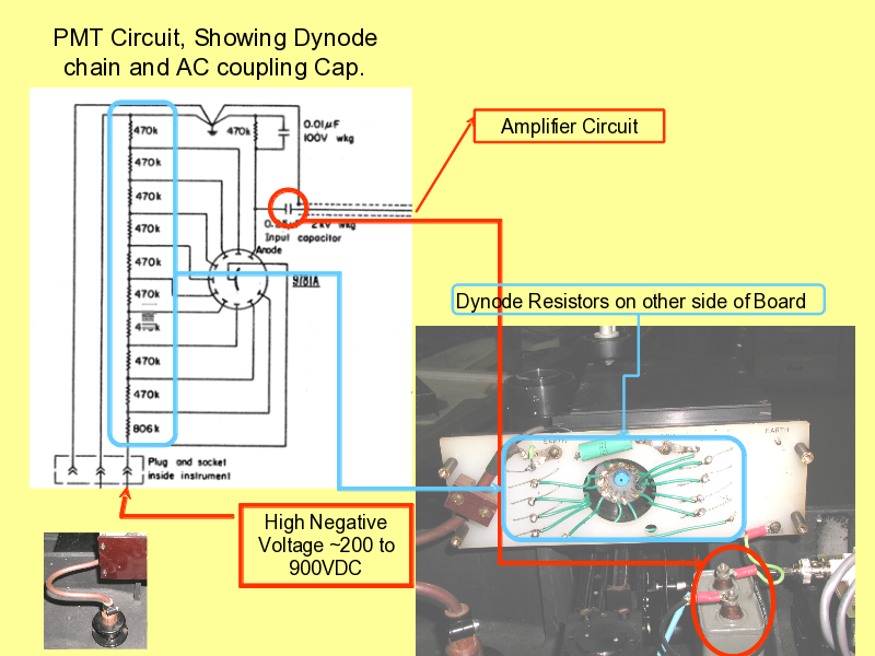
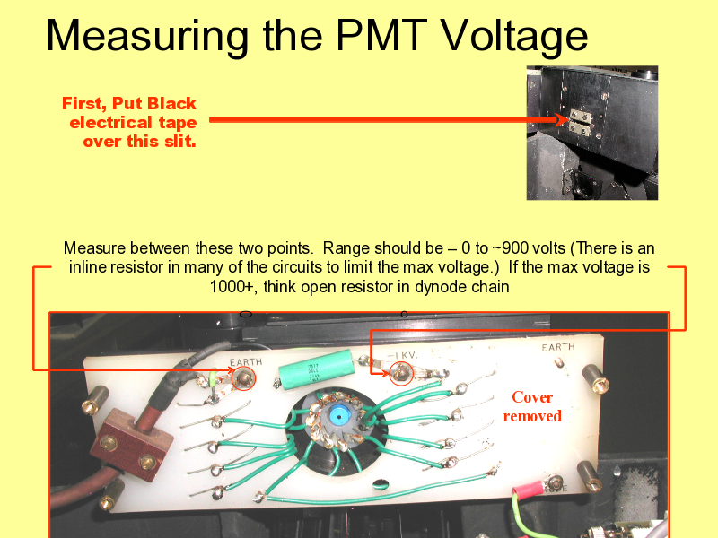
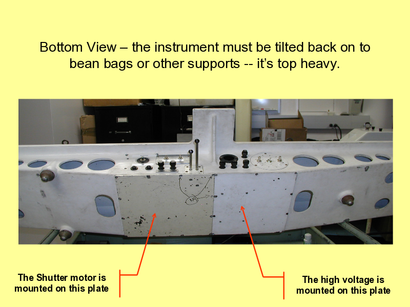
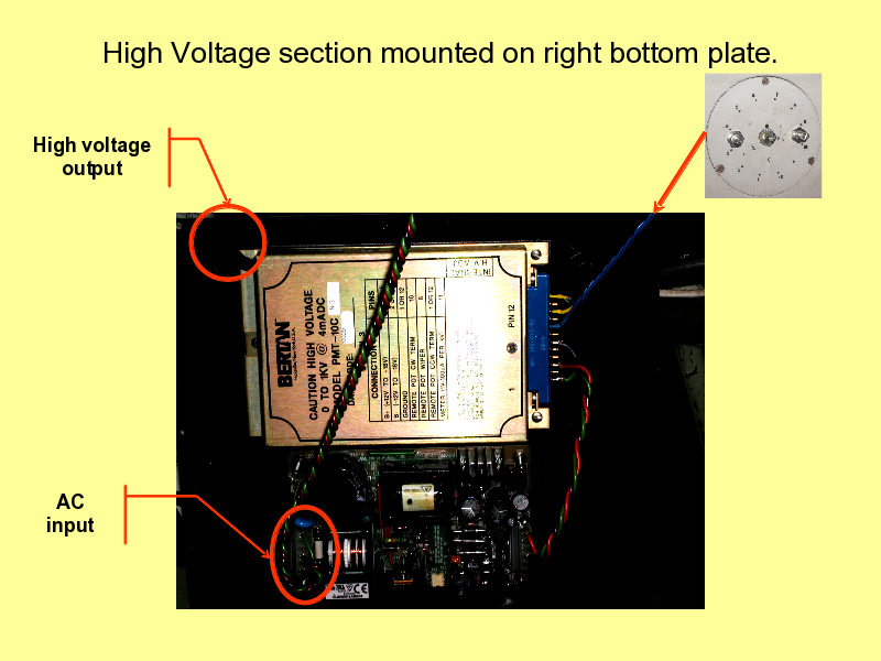
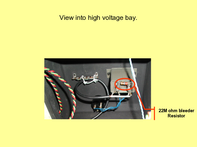
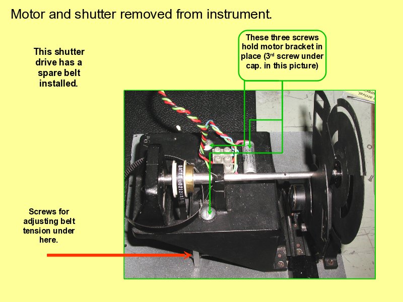
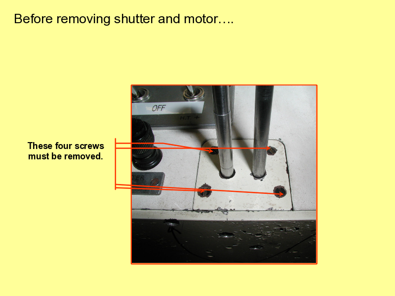
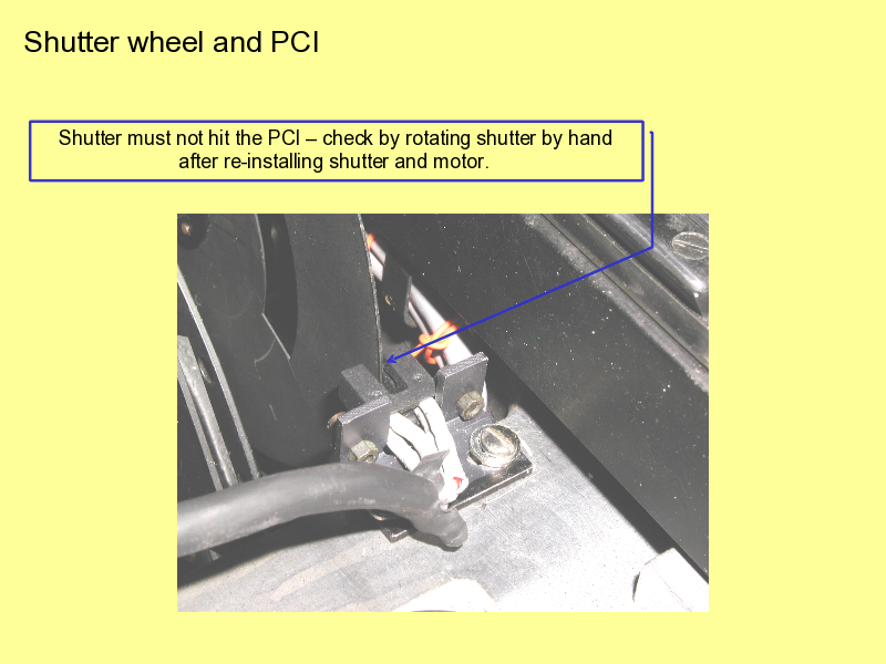
Table of contents
- (1) - Dobson Troubleshooting Guide
- (2) - Definitions
- (3) - Theory of operation
- (4) - What can go wrong?
- (5) - Getting started.
- (6) - Photomultiplier Tube Problems – There aren’t many.
- (7) - R-dial (optical attenuator readout) and Q-levers (Wavelength selectors)
- (8) - Ground Quartz Plate (GQP) and inlet window
- (9) - Cleaning
- (10) - Removing the Encoder
- (11) - Barrel (Bellows) connector access: Note that there might be two setscrews.
- (12) - Leveling the Encoder to the R-dial
- (13) - Problems with Encoder/Counter
- (14) - There are pins at each end of the lid (under the rings)...
- (15) - Removing the lid – After removing the encoder.
- (16) - Fuses – 3amp slow-blow.
- (17) - AC Power and switches – each section is independently switched.
- (18) - Block Diagram of Electronics
- (19) - Block diagram of the amplifier circuit.
- (20) - Block Diagram of the High Voltage Section.
- (21) - 1999 vintage amplifier circuit
- (22) - Locating the amplifier
- (23) - Amplifier Section
- (24) - Another view of amplifier card
- (25) - Quick Test of the amplifier
- (26) - PMT Circuit, Showing Dynode chain and AC coupling Cap.
- (27) - Measuring the PMT Voltage
- (28) - Bottom View – the instrument must be tilted back on to bean bags or other supports
- (29) - High Voltage section mounted on right bottom plate.
- (30) - View into high voltage bay.
- (31) - Motor and shutter removed from instrument.
- (32) - Before removing shutter and motor….
- (33) - Shutter wheel and PCI